Installing Solar

I installed a 4kW solar array.

In an effort to address my eco-anxiety, and reduce our carbon footprint and save money long-term, I installed solar panels on our roof. This was an extensive project, though. The first step was replacing the old roof. We didn’t know how old it was, and it was showing plenty of signs of wear, so we hired a contractor to install a standing-seam metal roof, which minimizes penetrations, is much more energy efficient, lasts a super long time, is recyclable, and since the old shingles were left in place it added much less landfill waste. The installers were able to do it in a day, and a month later there was a hail storm with 1″ stones that damaged every house in the neighborhood except ours. That was a fortuitous decision for us. We have also already seen a reduction in our energy costs because of the better heat management and venting of the roof. The second floor is a lot more livable now.

The newly installed blue metal roof. Looks great!
A panorama of the top of the roof on the back side. This is the south facing side and has a much lower pitch.

With the roof complete, I ordered the solar panels from a wholesale company that put together the plans for us to submit. There were some challenges with that, and they shipped the parts before I had city approval, which was an issue because the city rejected the plans immediately. It turns out that the plans didn’t include structural drawings, and the wholesale company wanted a lot of money to generate them. After talking to some people, it turns out that our existing roof was woefully undersupported. We found out from our neighbors that when the neighborhood was built, many of the houses were designed with expansion in mind, and that the basic floorplan could have a low pitch roof and be only 1 story, a high pitch roof and have a small second floor, or a mixed pitch roof and have a larger second floor. It turned out that the rafters for our house had been for the high pitched roof, but then shifted to a low pitch to make room for the second floor. HOWEVER, this made them overspanned (too much load on a 2×6 across a long horizontal area), AND because they were originally cut to 45 degrees at the end, and moved up to 12 degrees, there was a huge gap between the rafter and the top ridge board. The whole top of the roof was sortof unsupported. Whether or not solar was going to happen, I needed to fix this problem, and we had JUST gotten the new metal roof installed.

A view up into the attic. The left side of the ridge board is the 45 degree front pitch with rafters flush against the ridge board, and supported by a knee wall in the middle. The right side is improperly cut 2×6 rafters that span far longer than they are rated, with 1×8 boards scabbed on for some reason. This shouldn’t be standing.

After a lot of research and calculations, I managed to come up with a plan to sister new rafters to the old ones using fancy MSR2400 rated 2×6 boards, which are much stronger than the older ones and rated for the span I needed. I had to special order them, but the plan was approved and I could move forward.

The approved plan I drew up involved sistering new fancy rafters to the old insufficient ones.

For many days I would spend an hour or two up in the rafters. I had to cut them to size outside, then slide them in through the gable vent on the side of the house, then maneuver it into place, jack it up to take on the load, and bolt it to the ridge board and the sister rafter. It was hot and exhausting and difficult to move in a small space, and I had a watertight tyvek suit that was constantly wet and a respirator that made me fear drowning in my own sweat, but I got it done. The inspector was simultaneously impressed that the roof had managed to not cave in before, and impressed that I had been able to do what I did.

Sliding the rafter into place. Each one had to come in through the vent at the far end, then rotate into place.
I inserted new machine graded 2×6 lumber designed to span the correct distance, and sistered them with lag bolts to the previous rafters. These were cut at the correct angle and properly fastened to the ridge board. It took many hours of work to get each board in place, working in very cramped spaces, and the mask was necessary because of the fiberglass insulation.

With the rafters installation complete and the roof secure, I could focus on the actual solar installation. I’d had the parts in the garage for a few weeks, and it was getting colder and colder, so I was anxious to get it all installed. This part went fairly smoothly in comparison to the rafters. The racking went up in a day, the panels in another. I tied a rope to each panel and slid it up the 45 degree side of the roof on top of a blanket, easily pulling each of the 10 panels up to the roof. After that I worked on the wiring.

Sliding the panels up the steeper side of the roof.
Installation of the racking is complete, using a fastener that doesn’t penetrate the metal, allowing for a long-lasting roof. The first few panels are up, too.
All of the panels are on, and we’re ready for the electrical work.

It was my first time doing EMT conduit, and it was somewhat obvious in places, but I got it done. Everything was in place, and the inspector came to check it out. Unfortunately, I failed the first inspection, for some pretty minor things. I ordered some parts that afternoon, they arrived the next day, I installed them the day after, and then she came back for another inspection two days after that. Then I passed with flying colors, and she told me what a good job I had done. As a gifted millennial, getting that kind of validation and a literal report card from an authority figure, that really hit the spot. I buttoned everything up, set up the last of the web-based portion of the installation, and turned it on!

The plan for the electrical work. It was pretty easy to follow, and the actual implementation looks exactly like the plan.
The side of the house shows the conduit carrying the power down from the solar panels into the basement to the combiner box, then out to the external disconnect, then back in to the main service panel. Lots of conduit bending! In the top left you can see the vent through which all the rafters were inserted, which hasn’t been nailed back in place yet. Ask me how I got the rafters in there!

Conclusions

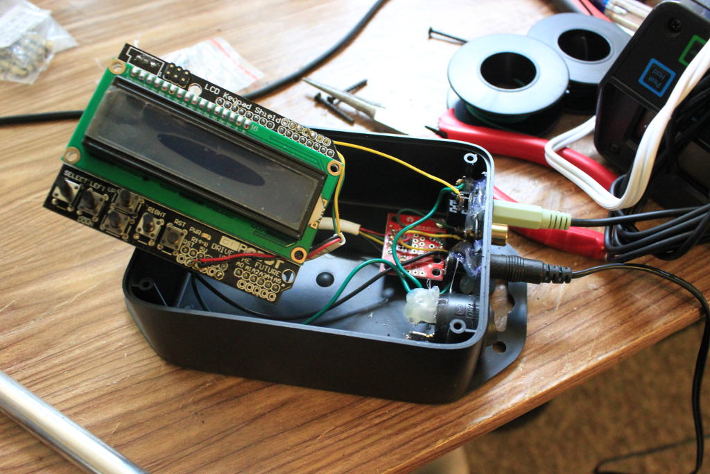
We’ve had an energy consumption monitor running for a little over a year, which was intentional as I wanted to design an appropriately sized solar installation. As designed, this will offset over 90% of our consumption over the last year. We have net metering, which means in the winter we should use the extra power from what we generated in the summer. Since I just turned it on there’s no immediate metrics worth sharing.

Repairing the rafters was tough but necessary work. Anybody else would probably have taken off the roof and come in from the top, which would likely have taken less time and been more sound, but also cost a lot more and risked damaging the roofing material we had JUST installed. The solar installation itself was pretty easy in comparison, and while the wholesale company I worked with was a bit of a pain in the ass, and they didn’t provide much in terms of instructions needed for the electrical portion, it still came together OK.

The overall cost is outlined here:

Permits$71
Unbound Solar (wholesaler package)$10125.05
Other Parts$794.65
Lumber$468.54
Total$11459.24

Our current consumption is roughly 5475kWH/year, and the PVWatts calculator estimates we will generate 5084kWH/year. With the lower AC needs thanks to the improved roof, we may end up at 100% of our consumption instead of ~90%. Since electricity is currently about $.16/kWH, this amounts to savings of $876/year, putting breakeven at 13 years. OUCH. And that’s a lot lower of a cost than if we had paid someone else to install. It’s very possible that energy prices will increase, lowering our breakeven point. But the big kicker here is the tax incentive we get, which is 30% of the installation cost. That brings our total cost to $6875.54, with a breakeven of 8 years, which is a lot more reasonable, considering the panels are guaranteed for 20.

Building My Bed

Since moving in, I had planned to have a Murphy bed, and style it in the same theme as the rest of the room; spacey without any specific branding. Here are the after photos. Continue on for the full process.

To start, I modeled it in CAD, and here are some renders:

From an angle. While the render shows hollow space, the intent was to put lighting and acrylic in the gaps.
From the bottom. The horizontal pieces will be lit, and the lower one will hold a piece of artwork by my sister.
The bed in its flat position.

When I purchased the materials for doing my basement renovation in 2019, I also purchased four sheets of 1/2″ plywood and stored them at Sector67. They were there for more than two years until I finally got around to doing the project. And it turned out I was one sheet too short. I had to pick up a fifth.

The design involves the bed and the sled, where the bed is 1/2″ plywood 61″x79.5″, with 4″ high walls made out of 1/2″ plywood. While a queen size mattress is 80″, the space where the unit will go is only 80″ tall, and I needed room for the walls. Additionally, it turned out that the space is sloped slightly, so I didn’t even have the full 80″, and my 1/2″ margin was completely eaten up, making sliding it in to the space a little difficult. Fortunately the mattress still fit into the 78.5″ space. The sled part is 4 sheets of 1/2″ plywood stacked together, with the inner pieces having cutouts that are larger to accommodate the LED strips and screws for the acrylic.

The various components.
The CNC panel router at Sector67 made quick work of all the cuts.

I used the CNC panel router at Sector67 to cut out all of the pieces, which gave me very accurate and very smooth edges. After that I sanded and built the bed portion, using screws and wood glue, clamping it together while it dried and I put in the screws, allowing me to re-use the clamps elsewhere. I used 1 1/4″ wood screws, and countersunk the holes pretty deep so that after everything I could use wood filler to cover up the holes. For the sled portion I glued and screwed 3 of the sheets together, leaving the 4th off so that I could install the electronics. I sanded everything to 220 grit and painted using oil-based primer, then sanded everything again. With the sled and the bed separate still, I painted the parts with a alkyd paint with a couple coats. Then I screwed the bed onto the sled, but left the countersunk holes exposed in case the two ever need to be taken apart for transportation. I’m confident that it would not fit out of the basement unless taken apart.

Screwing and gluing three sheets together, leaving the fourth off so I could install electronics.

I experimented with a few options for the acrylic, trying to rough up the surface of clear acrylic, spray painting the back side, and trying out other materials, but it turned out the best option was translucent acrylic. A single 4×8′ sheet was plenty for everything, and I cut everything 1/4″ inset so there would be plenty of space for screwing it in, plus room to get it in around the light strip, and some slop in case I didn’t align it properly. I used the laser cutter at Sector67, which made quick work of it.

For the light strips I used basic 12V RGB light strips, and two WiFi controllers. I wanted to be able to control it from my Alexa or the IR remote, just like the other strip lights in my room. However, I only wanted one outlet, and I wanted it to be a neatly enclosed box, so I took them apart and wired the power supply to deliver to both, then put them in a spare project box I had and mounted that to the sled. The tricky part is that it had to be in a location where it was out of sight and wouldn’t have any problems when up or down. Inside the sled I routed the strips and drilled 1/2″ holes through the small parts. I was able to route a whole side of the sled with one continuous strip, then use some wire to route to the other side through the middle of the sled, then use another single strip to route the other side of the sled. The other controller routes up to the horizontal pieces. I put a piece of translucent plastic in the center of the horizontal pieces to support the large acrylic pieces, especially since one of them could have significant weight on it from the art piece. Finally, since the adhesive of the light strips isn’t that great on wood, I used staples every few inches and especially in the corners to hold the strips in place. This was very difficult, as the staple gun was too wide, so I needed to hammer in each staple individually, and they didn’t like that. Additionally, if you nick the strip even the slightest bit, you risk shorting a section of the strip, so I ended up needing to do some surgeries to replace a few sections.

Once the wiring was done, and the acrylic was attached to the wood, I thoroughly vacuumed the insides, and closed them up, drilling and countersinking holes, then clamping them together while I screwed to minimize any gaps. I painted immediately after to make sure the inside was sealed from dust ingress. After a couple coats, everything was done.

After assembly I did additional coats of paint to hide the lines and screw holes and other blemishes.

The final part of the process was attaching the art piece my sister Betsy had done, and putting a strap in to hold the mattress and prevent it from falling out. The strap was easy enough; I had plenty of leftover webbing and clips from Wacky Dancers, and it’s not even noticeable under the fitted sheet. For the art piece I drilled a hole in one leg, then smoothed a face of a joint that made contact with the bed and drilled and tapped a hole in the face. Then I drilled a hole in the bed and put a bolt into the art piece. This way the art piece would stay in place when the bed was in either orientation, and the sled was designed intentionally so that the art piece would have a little bit of clearance so it wouldn’t slide against the carpet.

The mattress could fall out when upright, so I attached a strap that sits underneath the fitted sheet. You can’t even tell it’s there.

That’s it! After connecting it to my Alexa, everything was complete. The bed sits tucked under the HVAC bulkhead and opens up a lot of floor space in my room. It’s not very light, but I can manage to get it up and down. Springs or pneumatics aren’t really an option because the bed has no extra vertical clearance.

The final product again.

Here’s a breakdown of materials:

ItemCountCostExtended Cost
1/2″ 4’x8′ BCX sanded plywood5~$40$200
1/4″ 4’x8′ white translucent acrylic1$80$80
Dutch Boy Platinum Plus Cabinet, Door & Trim White Satin Paint, 1 Gallon1$48$48
Conco Pro Step One P008 Interior Alkyd White Quick Dry Stainblocking Primer/Sealer1$27$27
#6 1/2″ Flat Head Wood Screw 50ct1$2.17$2.17
#6 1/2″ Zinc Pan Head Construction Screw 50ct2$2.10$4.20
#8 1 1/4″ Phillips Flat Head Wood Screw 100ct1$5.09$5.09
#8 3/4″ Phillips Flat Head Wood Screw 150ct1$5.09$5.09
Heavy Duty Staples1$5.98$5.98
Titebond I Wood Glue 16oz1$4.38$4.38
Smart WiFi LED Controller with 24-key remote for RGB Light strip2$9.99$19.98
RGB LED Strip Lights 5M 300LEDs 12V3$13.99$41.97
Power Supply, 12V, 5A1$12.99$12.99
Total:$456.85
ToolOwner
CNC Panel RouterSector67
Table SawSector67
Belt SanderSector67
Corded DrillSelf
Various ScrewdriversSelf
Paint brushesSelf
SandpaperSelf
N95 RespiratorSelf
EarmuffsSelf
6in Bar ClampsSelf
Painter Drop ClothsSelf

Side project – Mallards Fast Pitch

My hackerspace Sector67 was approached this winter with a problem; the local minor league baseball stadium (Madison Mallards) fast pitch sign was old and no longer working, and they wanted some help fixing it up. In exchange for our expertise, they promised significant advertising and publicity, and they would have us be special guests at a ‘maker’ day during the season.

For the impatient, here’s the finished product:

final_close

We took them up on the offer and had a field trip to the stadium to see what was already there. There are two main parts to this project. First, there’s the sign itself. Second, there’s the press box, where the radar gun and the sign controller sit. The previous method was to have the person running the scoreboard watch the radar gun and type the speed onto a controller. There was no accounting for the angle of the radar gun, and it required a person to act as the middle man. They wanted to automate this part of the process. With the sign, they wanted it to work again. After seeing their existing setup, it didn’t take long for us to decide they needed an upgrade and we would start from scratch.

The sign in right field. Doesn't look very big from this shot, but it's legible from the far side of the stands.
The sign in right field. Doesn’t look very big from this shot, but it’s legible from the far side of the stands.

Up close you can see it's a bunch of incandescent bulbs. They're not even covered! I wouldn't want to run into that sign while catching a ball.
Up close you can see it’s a bunch of incandescent bulbs. They’re not even covered! I wouldn’t want to run into that sign while catching a ball.

The electronics controlling the sign. This is basic and ancient stuff here.

Up in the press box, this is what controls the sign.

This is the radar gun. They have to charge up the battery (the handle) before every game. This is a pain.

The stadium let us borrow the radar gun, the only part of the process we intended to keep. Reverse engineering it wasn’t too bad. We were able to find a manual and figure out that the three pins coming out into the handle were two for the battery and one for a serial signal. Once we connected to this signal, it was trivial to decipher it (9600 baud ASCII text). We designed a 3D printed part that would take the place of the handle and supply power to the radar gun as well as grab the serial signal.

3d_printed

Yes, those are nails. They worked perfect.

After that was the box to replace the controller. This box would read in the serial signal, compensate for the angle, and send out a signal to the sign. At first we played with XBee for a wireless transfer. This ended up being so unreliable and so difficult to get set up that we decided to give up. Besides, long term support is important for this kind of a project, and something wireless is a lot more difficult to diagnose and debug than wired. So we went with RS485, which is perfect for long distances, and there was already a pre-existing cable from the previous sign. I threw in a screen and some buttons for good measure (to let the user adjust the angle), and a switch to turn it all on, and we were good to go. Now the only thing a user has to do is flip the switch to turn it on, then push the power button on the radar gun, and it works.

The view from the press box. The radar gun captures every pitch, the controller box is mounted on the wall, and the previous controller is wrapped up on the desk.

The controller box. There's a screen, buttons, and power switch. The cables are for power in, power/serial to the radar gun, and RS485 out to the sign.
The controller box. There’s a screen, buttons, and power switch. The cables are for power in, power/serial to the radar gun, and RS485 out to the sign.

Inside the controller. An arduino with LCD/button shield, a RS485 breakout, and wires.

Next was coming up with a sign. We’ve used the P10 red LED modules before on the bar bike, so we had some experience. For this one we purchased the outdoor waterproof ones. We also got power supplies and a controller card. There is some code on the web for controlling these guys directly, but it’s a lot of work and I didn’t have the time or inclination to figure it out. So we went with the controller card. I should note that the prices for these parts is ridiculously cheap. The LED modules are $6.50, the power supplies are $8, and the controller card was $50. So we had all the major components for the sign for just a few hundred dollars, and that’s because we ordered extras of everything in case of failures. We designed and cut an enclosure and attached the modules to the frame, then wired everything up. The wiring is simple; power up each column, data across each row. Two power supplies power two columns each.

Behind the sign. Two power supplies, one laptop, a controller card and hub, and a laptop. The sign is 6 rows and 4 columns, giving us a resolution of 128x96
Behind the sign. Two power supplies, one laptop, a controller card and hub, and a laptop. The sign is 6 rows and 4 columns, giving us a resolution of 128×96

Getting the controller card working was tricky, though. There is no documentation on the protocol, so I tried sniffing the packets being sent to it, but couldn’t make sense of them. There was no API, and after repeatedly pressing the Chinese company for resources, they sent some sample code and a dll, but it would only work on windows. We were trying to avoid Windows and go with a cheap (and low power) linux PC or Raspberry Pi, but in the interest of time, we ended up bailing on that and just getting a very old and cheap Windows XP laptop. Fortunately, it had a serial port, so we could hook a RS485 to RS232 converter to it and we were able to communicate quickly with the press box.

The controller card comes with some windows software for setting up the sign and displaying content, but it was difficult to get it to show real time data. What we ended up doing was writing a python script which would monitor the serial port and upon receiving a speed would write that speed to a file. One of the options in the other software for controlling the sign (called LEDSHOWT9), was to display the contents of a file, and update every N seconds. So we picked that option. Now every few seconds LEDSHOWT9 will look at the file, and take the contents (either the speed or a blank), and show that on the sign. Tada! It’s a hack, but it works. If inclined, maybe I’ll write up something better and do animations or something. But probably not.

Here’s the final product.

Clearly visible during the day from the stands. Pretty font, works automatically. Complete success.

A Kalahari Christmas

After Erin took me on a ski trip to Salt Lake City for Christmas 2010, I was far behind in the Christmas Karma. For 2011 I planned to take her to a resort in Wisconsin Dells, which is sort of like the Las Vegas of Wisconsin, except with water parks instead of casinos.  Of the many resorts, I decided on Kalahari based on recommendations of others and some research on the web. But just telling her wasn’t a great way to do the presentation. I wanted her to unwrap something.

I’ve been working for a while on a portable electronic scoreboard, so I had all the materials to make a good LED sign with the name. The day before we were to leave for Kansas, I started the project. The idea was to make a big LED sign that said Kalahari on it. It would be battery powered, and a switch would turn it on when the box was opened so that it wasn’t on the entire time and running out of battery. That was as far as I got in planning before I started building.

I borrowed a rechargeable battery from Sector67 to use as the power supply, then laid out the LEDs on a prototyping perf board covered with sticky black nylon paper. It took a couple tries to get it all to fit on the available board with legible letters and decent spacing. Then I found a switch that would work. The circuit was simple. The switch connected the + voltage to the board and the ground went directly to the board. The LEDs were connected with a resistor and two LEDs in series, and all those strings were in parallel. This meant a huge current drain, but I was limited to a power supply with only 6 volts, so I didn’t have much choice. This also meant a LOT of soldering and a lot of current limiting resistors. There was an odd number of LEDs, so I put an extra one on the back side so that the circuits were all the same.


With all these LEDs packed into a small space, it was very bright, so I struggled with a few different ways to do the presentation. I ended up taping the board behind a piece of paper so that the paper would diffuse the light a little. It ended up working great. The paper covered everything, including the switch. When the box was closed it was off, and when it was opened the switch was triggered, turning on the sign.

The girlfriend was happy, so the project was a success.

The next time I do something like this I’ll use less LEDs and instead of doing a sign of LEDs I think it would be better to have a piece that had letters cut out and was backlit by only a few LEDs. I also would have spent a lot more time on what was surrounding the sign. Using regular paper and crayon to draw was the best I could do with the limited time and resources I had, but it wasn’t enough for me. Construction took far longer than I expected, and I was a little disappointed with the results. I was working late into the night to solder it all together, and I barely had any time to work on the rest of the package. I can do better.

Fast Scanner

Since I’m moving in a few months to an apartment of significantly reduced size, I am starting to reduce the size of my collection of stuff. One thing I’ve been carrying around is everything from my college career. I have every syllabus, paper, homework assignment, handout, midterm… in total it was three boxes full of binders. This represents tens of thousands of dollars of education, though, and I wasn’t entirely willing to part with it. I started scanning pages with a scanner. I had a process that was giving me up to 6 scans per minute. The quality of the scans was good, but the speed was not fast enough, and there were too many manual parts to the process. I needed something faster.

I realized that a photo of a piece of paper would be faster than having a scanner do it, and if lit well enough and with a good enough lens, it would be just as good as a scanner. I rigged up a tripod with an extended arm to hold my camera, and I put a white background on the desk and marked some lines where the paper needed to be to be in the shot. Since I don’t have a fancy DSLR with a remote, and pressing the button manually was way too much effort and moved the camera around too much, I rigged up a piece of twine so that by pulling down on the twine I could get the camera to take a shot. I tried pulling the string for a while, which was pretty fast, but still not as efficient as possible. I tied the twine to a ruler and used the ruler as a foot pedal, giving me both hands to move the pieces of paper as quickly as possible. The light sources were just regular white compact fluorescent bulbs, placed to put as much light on the paper as evenly as possible.

The resulting contraption bumped my speed up to 15 pages per minute on average. Sometimes it was higher depending on if I was dealing with loose notes or stapled sheets. Having the shutter controlled by my feet gave me a huge advantage, and I was able to fly through all 3 boxes of papers in a few evenings much faster than I expected. Now I have it all on my computer, which should probably still be sorted, but at least it’s not taking up any physical space, and I don’t have to feel any sense of loss when I recycle my stacks of papers.

Mouse Modding

Last night I made some changes to my mouse; we’ll see if they’re improvements or not. Originally I was dismantling it to clean it. Something had gotten inside the wheel and was causing it to scroll inconsistently. Once I got inside, though, I saw an opportunity to tune it.

First was the clicking on the wheel. This is accomplished with a spring, and is sometimes annoying, especially since I like to give my scroll wheel big long spins to quickly move around on a page. Removing the spring was pretty easy.

Second, I noticed a weight added to the inside. I’m not entirely sure what the weight accomplishes, other than making the mouse that much harder to move, so I took it out, too.

If I need, I can easily put the parts back in, but at the moment I’m rocking a lighter, smoother mouse.

image

Broken Car Lock

It’s no secret that I love my car. It’s been extremely dependable, has treated me very well, has a good personality and an adventurous attitude, and doesn’t ask for much (it’s a 2000 Chrysler Neon, and yes, I mean Chrysler). I’ve had it for almost 10 years and put over 100,000 miles on it myself in addition to the 20,000 that were on it when I got it used. If I were to get another car, I’d look for something exactly like the one I have.

But once in a great while it will have small issues. Once a wiring harness broke loose and cause the rear lights to go out. Other than that, it’s worked very well and could probably go for another hundred thousand miles without problem.

About a week ago I put my key in the door to unlock it and found that it turned freely. I had to unlock the passenger side and then unlock the driver side from the inside. For a few days I drove around without locking the door. Monday I finally got an opportunity to examine the problem. I was able to disassemble the door relatively easily. It was fairly straightforward except for the part where the window handle was connected, but I managed to find the service manual online and pop the handle off. Then I could get in to the lock mechanism and see where the problem was. It didn’t take long to discover the problem. The rod that connects the lock mechanism to the key had slipped off. The piece that held it on was missing. Figuring it was probably at the bottom of the door frame, I felt around and identified it. Yep, there was the problem.

That piece should be symmetrical. The piece that had broken was about 2 millimeters wide and because of that the thing slipped off the lock and was no longer holding the rod in place. It didn’t take much jostling for the rod to fall out.

I didn’t have any parts exactly like that, and I was up to the challenge of fixing it with parts that I had around the house. I made a crude washer out of a piece of scrap tin from a can. Then I made a springy curl of stiff wire that would take the place of the part that broke. I installed onto the lock mechanism and played with it a little to make sure it was stuck pretty well. I tried to take it off to adjust it a little, but couldn’t even get it off without some serious effort, so I just left it on there. I tested it thoroughly before putting the door back together. With the door completely reassembled, I tested it out some more, and it worked exactly like it had originally worked.

I’m kind of glad that my car is mostly mechanical and doesn’t have a lot of electronic parts. Electronic locks or windows would have made this a much more difficult operation. I’m also happy that I was able to build the parts that I needed from scratch and basic tools. Plus, I always enjoy doing things with my hands and seeing the results and saving money in the process.

Camera Troubles

Erin handed me a camera a week ago that had gone through some tough times. It had been dropped while on, and the lens assembly was broken and askew. The camera couldn’t recover from it on its own, and so I was brought in to see if I could fix it. Having been able to revive Erin’s camera, which had the misfortune of a drop into sand, and having removed dust from my own camera many times, I took on the job. Since it was already broken, the owner of the camera didn’t have any expectations of getting it back anyway, so it was a riskless job. The first image is of the camera, though the lens problem is not visible.

Taking the camera apart was not difficult. There were lots of tiny screws, but for the most part the pieces separated fairly easily. Of course, as I did it I learned little bits about the assembly that made taking it apart easier. The second picture shows the partially disassembled camera. The lens assembly came out without any screws.

The lens assembly out, I was able to partially disassemble it as well. There were two main lenses. The first was the big one in the picture below. The second was the small one in the picture below that. Both were capable of moving.

In fact, it was the plastic on the smaller lens that had broken, and was sticking out, preventing the lens assembly from closing back up. This little piece of plastic, which is the part closest to the camera, turned out to be extremely important. I tried at first to just remove it and reassemble the camera, but it turned out that it wouldn’t focus without it. The piece was essential for guiding the lens forward and back and without it a small spring was pulling it in a direction it shouldn’t have gone. I was able to super glue it back together, but then had to take a small file to remove small jutting slivers that were adding too much friction to the assembly. The hardest part was putting the whole lens assembly together and back apart over and over, which took many minutes each time, and put wear and tear on some components that were only ever meant to be assembled once. In fact, a great deal of time was spent maintaining and guiding parts back together, and resetting springs that had to be unset.

I thought that I had been successful and had fixed the camera, but there was a problem. When I took a photo, the iris would stay closed, and it wasn’t until I would dismantle the whole thing that I could reopen the iris. Clearly this would not work in the field. I had to dismantle the assembly further to discover another unfortunate break.

The iris is controlled by two extremely small electromagnets, which apply torque to two magnets, which have small arms at the end of them. Those arms push and pull the thin pieces of plastic over the lens to adjust the light levels. Unfortunately, one of the arms was broken on the small magnet.

This was the deal breaker. Without the arm, the iris wouldn’t function properly, and the images would be overexposed (or possibly underexposed). The magnet wouldn’t take to super glue, and even the process of gluing was made more difficult by the fact that all my tools were metallic and would move the magnets as soon as they got near. For a sense of scale, the pic below is of an object that’s 4mm long at its longest

It took a lot of time to work on the camera and figure out how it all fit together. There were a lot of little pieces that had to be assembled just so, and it’s such a shame that the camera is perfectly good except for a few misplaced atoms, and because I won’t be able to find a replacement will now likely be discarded in its entirety.

TV Remote Alarm

We had an interesting problem at work. There’s a display in the main lobby of my building that shows the calendar of all the conference rooms and a map showing where they are in the building. It’s pretty handy for visitors and looks really slick. The problem, though, is night. There’s no point in having the display running 24/7. But the TV has a flaw where it won’t go into sleep mode when the HDMI cable is plugged in, even if the computer itself is asleep and there isn’t a signal.

The solution so far has been for a select few to turn it on in the morning when they arrive and off when they leave. Naturally, this isn’t a sustainable or reliable solution, as it doesn’t take a lot for the system to break down.

So Ian brought me in on the problem to see what I could do with it. I thought about some existing options. An outlet timer would work for turning it off in the evening, but not for turning it on in the morning (it would give the TV power, but not turn it on). I even found an alarm clock that was capable of being programmed to turn on and off a TV, which was really close to what we wanted, but it was discontinued, and reading into the manual it looked like it wasn’t going to work anyway.

I realized I would have to build something. I started off thinking of building off of the Arduino microcontroller board, which I’ve used for other projects and really enjoy using. I spent a day working on hooking up an infrared LED and trying to get it to output a standard on/off signal that the TV would recognize. I also tried to hook up an LCD screen and buttons for configuring the timer, but I quickly got frustrated as each part took way longer than I wanted, and wasn’t getting anywhere.

It made a lot more sense to work with existing electronics and cobble something together. It turned out I already had an alarm clock that I had stopped using in favor of my cell phone, and the alarm clock had two configurable alarms on it. And Ian had purchased for me a cheap universal remote. So I just had to get the alarm clock to trigger the remote control.

This was easier said than done. First I took apart the remote control. I followed the traces back from the on/off button and soldered a couple wires to them, then fed them out the back of the remote through a hole where the battery cover was. Next, I opened the alarm clock and went about trying to identify triggers I could use to determine the alarm state. I was hoping for something simple, like one node being +5V when the radio alarm was on and a different node being +5V when the buzzer alarm was on. Sadly, there was no such luck.

I’ll spare most of the details, but I never found a clean signal I could use. I ended up taking the radio alarm, cutting out the speaker, turning the volume all the way up, and using the speaker wire to drive two relays, which triggered the remote, then also fed to the alarm reset button. That way the radio would turn on, the signal would trip the remote, and it would reset the alarm. That one worked pretty slick.

It was even harder for the buzzer alarm. Not only could I not find a signal, but it didn’t go to the speaker, either. It went to a separate piezoelectric speaker, and the voltage to it wasn’t enough to trip the relays. So I had to build an amplifier circuit that bumped the signal up to something that would trip the relay. But then there was another problem. It was tripping the alarm reset button faster than it was tripping the remote, so it’d reset the alarm before the remote control had a chance, and the TV wouldn’t ever get switched. I fixed this by putting in an RC delay circuit on the alarm reset relay.

I put it all back together and tested it out. It’s in my apartment, so I had to try it out on the VCR (I had to take it out of its box), but it worked. The alarm clock dutifully turned off and on the VCR at the right times.

I’m bringing it in to work tomorrow to see if it’ll work on the intended television. It’ll probably sit on a counter across the lobby and point at the TV, and definitely have a sign that says what it is so people don’t get suspicious.

Here’s a picture of the completed project. I won’t show the insides because I’m a little embarrassed of the circuit. I could have done a much cleaner and more correct design, but it works now, so I’m happy. I hope people at work appreciate it, too.

Hard Drive Surgery

A friend of mine recently had a minor emergency when a portable hard drive was knocked off a table and ceased to function. I was called in to help. Indeed, it did not work. When plugged in (and I tried on multiple computers and operating systems), it wouldn’t be able to recognize the device.

Since there was nothing I could do externally, I opened up the case, careful to make sure that anything I did could be undone. The case wasn’t even screwed together; it was two pieces of plastic that snapped together. After unsnapping all the way around, the hard drive was exposed. Again, no screws. It was held fast with some rubber strips on the corners. There was a piece of aluminum foil covering the electronics, so I carefully peeled that back. Glancing at the board, I didn’t see anything wrong immediately. The board was attached to the hard drive, and was easy to pull off. It turned out, the hard drive was a standard SATA connection, so I turned off my computer, plugged it in, and turned the computer on. It had no problem recognizing the hard drive and mounting it. I created a folder on my computer and immediately copied all the files over without any problems. Next I compared the file sizes to make sure I had gotten all the files and they added up to the right size. After that, I turned off the computer and removed the hard drive.

Looking again at the board, I noticed a small part near the USB connection that was askew. Looking more closely, it was indeed broken off the board and hanging by only one of the four solder points. The board was so small, though, and the connections tiny. I tried heating up the soldering iron and getting in there, but there was no way I’d be able to resolder it on. Just too small. I told my friend the data was fine and that the board was not and that if she got another portable hard drive I could copy the files over to it.

She brought me a new portable hard drive, so I plugged it in, copied the files, checked the size to make sure it was all copied, and unplugged it. Then I brought her the new hard drive, the old one, and showed her the parts and what had happened. Since the hard drive was still good, it didn’t make sense to discard it. It’s a 120GB laptop hard drive. She’s going to confirm that everything is there, and then I’ll delete the copy of the data I have on my hard drive.

The whole operation was surprisingly easy, and it certainly helped that the portable hard drive was so simply designed and used standard connections. I’m glad we were able to recover everything, though a little disappointed I couldn’t resolder the part back on.